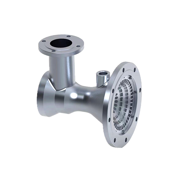
Factors Affecting the Working Efficiency of Ejectors
I. Geometric Parameters of Ejector Structure
Nozzle Design
Nozzle Throat Diameter (d₁): Directly affects the velocity of the motive fluid. An optimal d₁ (typically 0.05–0.1 times the suction chamber diameter) maximizes energy transfer. Deviation from the optimal value reduces efficiency by 10–15%.
Nozzle Contour: Convergent-divergent nozzles (Laval nozzles) for supersonic flows (M > 1) achieve 5–8% higher efficiency than simple convergent nozzles in gas ejectors.
Suction Chamber and Diffuser Geometry
Suction Chamber Diameter (D): Must match the motive fluid flow rate; a diameter too small causes excessive pressure drop, while a large diameter reduces mixing efficiency.
Diffuser Angle (θ): Optimal θ is 8–12° for liquid ejectors and 10–15° for gas ejectors. Angles exceeding 15° increase turbulence and energy loss, decreasing efficiency by 8–12%.
II. Fluid Properties and Operational Conditions
Motive Fluid Parameters
Inlet Pressure (P₁) and Temperature (T₁): Higher P₁ enhances the velocity of the motive fluid, but excessive pressure (e.g., >10MPa for liquid ejectors) may cause cavitation. For gas ejectors, T₁ affects the specific heat ratio (γ), with efficiency peaking at T₁ = 298K (room temperature).
Viscosity and Density: Low-viscosity fluids (e.g., water, η < 1cP) yield 15–20% higher efficiency than viscous fluids (e.g., oils, η > 10cP) due to reduced frictional losses.

Suction Fluid Characteristics
Suction Pressure (P₂): The pressure difference (P₁ - P₂) must exceed the critical value for effective entrainment. For water ejectors, P₂ should be ≤0.3×P₁ to maintain efficiency >70%.
Gas-Liquid Ratio (for Two-Phase Flow): In steam ejectors, the optimal steam-to-water mass ratio is 1:8–1:10; deviations reduce condensation efficiency and increase backpressure.
III. Fluid Flow Regimes and Thermodynamics
Compressibility Effects (for Gas Ejectors)
Mach Number (M): Motive fluid velocity should reach M = 1.5–2.0 in the nozzle throat for supersonic ejectors, maximizing entrainment. Subsonic flows (M < 1) reduce efficiency by 20–30%.
Shock Wave Formation: Uncontrolled shock waves in the diffuser (caused by excessive backpressure) disrupt flow stability, decreasing efficiency by 15–20%.
Cavitation and Two-Phase Flow (for Liquid Ejectors)
Cavitation Number (σ): σ = (P₂ - P_v)/(0.5ρv₁²) should be >0.5 to prevent cavitation. Cavitation erodes the nozzle and reduces efficiency by 10–15%.
Vapor Volume Fraction: In two-phase ejectors, the optimal vapor fraction is 5–10%; higher fractions cause flow separation and pressure pulsations.
IV. Operational Parameters and System Integration
Area Ratio (A₂/A₁)
The ratio of the suction chamber area to the nozzle throat area (A₂/A₁) significantly impacts efficiency. For liquid ejectors, optimal A₂/A₁ = 10–15; for gas ejectors, 20–30. Deviations from these ranges reduce efficiency by 8–12%.
Backpressure (P_b)
P_b must be ≤ the critical backpressure (P_bcrit) to maintain supersonic flow in the diffuser. Exceeding P_bcrit causes flow separation, with efficiency dropping by 15–25% when P_b/P₁ > 0.5.
